|
|
|
|
|
|
|
|
|
|
|
|
|
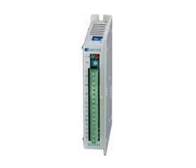
Q2HB44MC 2-phase stepper motor driver
|
|
| Model No.︰ | Q2HB44MC |
| Brand Name︰ | JB |
| Country of Origin︰ | China |
| Minimum Order︰ | 1 pc |
|
|
|
|
|
|
|
Q2HB44MC is a Constant angle, constant torque micro step driver, the drive voltage of which is from 12V to 40VDC. It is designed for use with the 2-phase hybrid stepper motor of all kinds with 42mm to 86mm outside diameter, 6, 8 leads, regulated phase current from 0.5A to 4A . The unique control circuit that it adopts can reduce motor’s noise, make motor run more smoothly, improve motor’s performance by 30% at high speed, reduce driver’s heating by 50%. It is widely used in the small numerical control devices with high resolution such as curving machine, laser labeling machine and etc. Features High performance, low price 12/8 channels constant angle and constant torque micro step, highest micro step: 200 A unique control circuit is adopted Highest response frequency: 200Kpps Current of winding will be reduced by approximately 50% when no step pulse command is received for 0.1 second Bipolar constant current chopping mode Opto-isolated signal I/O Drive current is continuously adjustable from 0.5A/phase to 4A/phase Single power supply voltage from 12V to 40VDC
Caution Please don’t reverse the power supply, supply voltage shouldn’t exceed 40VDC. Input control signal is 5V, current-limiting resistance should be connected when it is over 5V. Alarm indicator lights and the driver stops working when the driver temperature is over 70℃. It restarts working until the temperature falls to 50℃. The heat sink is needed when overheat occurs. 4.6 or 8 leads motors have to be used because of the special control circuit in the driver.
Subdivision (Micro step) setting for Q2HB44MC Subdivision (Micro step) setting for Q2HB44MD
Steps per revolution | 1 | 2 | 4 | 8 | 16 | 32 | 64 | 128 | D0 | ON | OFF | ON | OFF | ON | OFF | ON | OFF | D1 | ON | ON | OFF | OFF | ON | ON | OFF | OFF | D2 | ON | ON | ON | ON | OFF | OFF | OFF | OFF | D3 | Ineffective | D4 | ON, double pulse: PU is positive step pulse signal, DR is negative step pulse signal | OFF, single pulse: PU is step pulse signal, DR is direction signal |
Terminal function Symbol | Signal | Specification | TM | Working indicator | The green indicator lights when signal TM is effective. | O.H | Alarm indicator | The red indicator lights when overheat occurs. | Im | Rotary switch for adjustment of the motor current | Adjust motor’s phase current. Turning it in CCW will decrease the current and in CW will increase. | + | Positive of opto-isolated | Connected to +5V power supply. Drive voltage ranges from +5V to +24V. Current-limiting resistance is needed when it is over 5V. | PU | D4=OFF, PU is step pulse signal | With the falling edge of the signal PU, the motor executes an angular step. The input resistance is 220Ω. Low voltage 0-0.5V, high voltage 4-5V, pulse width>2.5μS. | D4=ON, PU is positive step pulse signal | + | Positive of opto-isolated | Connected to +5V power supply. Drive voltage ranges from +5V to +24V. Current-limiting resistance is needed when it is over 5V. | DR | D4=OFF, DR is direction signal | Change motor’s direction of rotation. Input resistance is 220Ω. Low voltage 0-0.5V, high voltage 4-5V, pulse width>2.5μS | D4=ON, DR is negative step pulse signal | + | Positive of opto-isolated | Connected to +5V power supply. Drive voltage ranges from +5V to +24V. Current-limiting resistance is needed when it is over 5V. | MF | Motor free signal | The motor current will be cut off and the driver stops working when it is effective. | + | Positive of opto-isolated | When the motor current is on, the motor is at the origin position. (B, -A is on current); opto-isolated outputs (high voltage). | TM | Negative of opto-isolated | Connected + to the current limiting resistance of output signal, and connect TM to ground. Maximum drive current is 50mA and highest drive voltage is 50V. | +V | Positive of power supply | 12-40VDC | -V | Negative of power supply | AC、BC | Connection | 
| +A、-A | +B、-B |
Steps per revolution | 1 | 2 | 4 | 5 | 8 | 10 | 20 | 25 | D0 | ON | OFF | ON | OFF | ON | OFF | ON | OFF | D1 | ON | ON | OFF | OFF | ON | ON | OFF | OFF | D2 | ON | ON | ON | ON | OFF | OFF | OFF | OFF | D3 | ON | ON | ON | ON | ON | ON | ON | ON | D4 | ON, double pulse: PU is positive step pulse signal, DR is negative step pulse signal | OFF, single pulse: PU is step pulse signal, DR is direction signal | Steps per revolution | 40 | 50 | 100 | 200 | 200 | 200 | 200 | 200 | D0 | ON | OFF | ON | OFF | ON | OFF | ON | OFF | D1 | ON | ON | OFF | OFF | ON | ON | OFF | OFF | D2 | ON | ON | ON | ON | OFF |
|
|
|
| Payment Terms︰ | Paypal,bank transfer,TT/LC/DP/DA |
|
|
Product Image
|
|
|
Related Products
|
|
|
|
|
|
|
|
|