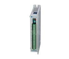
Q3HB64MA is a constant angle and constant torque stepper motor drive. The driven voltagerange from DC12V to 40V. It can match 3-phase hybrid stepper motors whose rated current is under5.8A and shaft diameter range from 42mm to 86mm. Owe to bipolar constant chopping circuit, it can make motors low noise and operated smoothly when low speed; the torque is much greater than 2-phase and 5-phase stepper motor when high speed. It is widely used in small-sized numerical control device such as medical machine, robot, instrumetation, curving machine, laser labeling machine, inner laser curving machine.
Feature
● High performance, low price
● 16 channels constant angle and constant torque, the highest subdivision is 60000 s/r
● Special control circuit
● Highest response frequency: 200Kpps
● The motor phase current is reduced to approximately 50% of the set current value 100ms after receiving the last pulse edge
● Bipolar constant current chopping circuit
● Opto-isolated input/output
● Driven current is adjustable continuously from 0.5A/phase to 5.8A/phase
● Single power supply, voltage arrange from DC12V to 40V
Caution
1. Don’t reverse the power supply, supply voltage shouldn’t exceed DC40V.
2. Input control signal is 5V, current-limiting resistance should be connected when over 5V.
3. Alarm indicator lights and the drive shuts off if the drive temperature is over 70℃. It doesn’t work until the temperature falls to 50℃. The heat sink is needed when overheat occurs.
4. Alarm indicator lights when overcurrent (short of load) occurs. Please check motor’s connection and other shorts and turn the power supply on after removing the trouble.
5. Alarm indicator lights when undervoltage (the voltage is less than DC12V) occurs.
Subdivision setting
|
Q3HB64MA s/r
|
400
|
500
|
600
|
800
|
1000
|
1200
|
2000
|
3000
|
4000
|
5000
|
6000
|
10000
|
12000
|
20000
|
30000
|
60000
|
|
Q3HB64MB s/r
|
400
|
800
|
1600
|
3200
|
6400
|
12800
|
25600
|
51200
|
51200
|
51200
|
51200
|
51200
|
51200
|
51200
|
51200
|
51200
|
|
D0
|
ON
|
OFF
|
ON
|
OFF
|
ON
|
OFF
|
ON
|
OFF
|
ON
|
OFF
|
ON
|
OFF
|
ON
|
OFF
|
ON
|
OFF
|
|
D1
|
ON
|
ON
|
OFF
|
OFF
|
ON
|
ON
|
OFF
|
OFF
|
ON
|
ON
|
OFF
|
OFF
|
ON
|
ON
|
OFF
|
OFF
|
|
D2
|
ON
|
ON
|
ON
|
ON
|
OFF
|
OFF
|
OFF
|
OFF
|
ON
|
ON
|
ON
|
ON
|
OFF
|
OFF
|
OFF
|
OFF
|
|
D3
|
ON
|
ON
|
ON
|
ON
|
ON
|
ON
|
ON
|
ON
|
OFF
|
OFF
|
OFF
|
OFF
|
OFF
|
OFF
|
OFF
|
OFF
|
|
D4
|
ON, double pulse: PU is positive pulse signal, DR is negative pulse signal
|
|
OFF, single pulse: PU is pulse signal, DR is direction signal
|
|
D5
|
Self detect switch (OFF: accept pulse input, ON: send out 7.5KHz pulse. The subdivision should be between 2000-10000 s/r)
|
Terminal function
|
Mark
|
Function
|
Specification
|
|
TM
|
Working indicator
|
The green indicator lights when TM signal is effective.
|
|
O.H
|
Alarm indicator
|
The red indicator lights when overcurrent, undervoltage, overheat occurs.
|
|
Im
|
Rotary switch for adjustment of the motor current
|
Adjust motor’s phase current. Turning it in CCW will decrease the current and turning it in CW will increase the current.
|
|
+
|
Positive of opto-isolated
|
Connected to +5V power supply. Driven voltage range from +5V to +24V. Current-limiting resistance is needed when over 5V.
|
|
PU
|
D4=OFF, PU is pulse signal
|
With the falling edge of the signal PU, the motor executes an angular step. The input resistance is 220Ω. Low voltage 0-0.5V, high voltage 4-5V, pulse width>2.5μS.
|
|
D4=ON, PU is positive pulse signal
|
|
+
|
Positive of opto-isolated
|
Connected to +5V power supply. Driven voltage range from +5V to +24V. Current-limiting resistance is needed when over 5V.
|
|
DR
|
D4=OFF, DR is direction signal
|
Change the motor’s direction of rotation. Input resistance is 220Ω. Low voltage 0-0.5V, high voltage 4-5V, pulse width>2.5μS
|
|
D4=ON, DR is negative pulse signal
|
|
+
|
Positive of opto-isolated
|
Connected to +5V power supply. Driven voltage range from +5V to +24V. Current-limiting resistance is needed when over 5V.
|
|
SM
|
Subdivision choosing signal
|
Work as the subdivision set by D0-D3 at high voltage and as half step (600s/r) at low level.
|
|
+
|
Positive of opto-isolated
|
Connected to +5V power supply. Driven voltage range from +5V to +24V. Current-limiting resistance is needed when over 5V.
|
|
MF
|
Motor free signal
|
The motor current will be cut off and the drive stops working when it effects.
|
|
+
|
Positive of opto-isolated
|
When the motor current is on, the motor is at the origin position; opto-isolated output (high level)
|
|
TM
|
Negative of opto-isolated
|
Connect + to current-limit resistance of output signal, TM to ground. The maximum current is 50mA, the highest voltage is 50V
|
|
+V
|
Positive of power
|
DC12~40V
|
|
-V
|
Negative of power
|
|
U
|
Connection
|
|
|
V
|
|
W
|