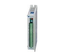
Q2HB44 full/half stepper drive, driven voltage range from DC12V to 40V. It can match 6 leads or 8 leads 2-phase hybrid step motors whose rated current under 4A, shaft diameter range from 42 to 86mm. It is widely used in small size numerical control device such as curving machine, wire stripping machine and etc.
Features
- High performance, low price
- Highest response frequency: 200Kpps
- The motor phase current is reduced to approximately 50% of the set current value 100 ms after receiving the last pulse edge
- Bipolar constant current chopping circuit
- Opto-isolated input/output
- Single power supply, voltage range from DC12V to 40V
Caution
- Please don't reverse the power input, supply voltage shouldn't exceed DC40V.
- Input control signal is 5V, current-limiting resistance should be connected when over 5V.
- Alarm indicator lights and the drive shuts off if the drive temperature is over 70℃. It dose not work until the temperature falls to 50℃. The heat sink is needed when overheat occurs.
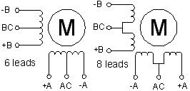
- 6 or 8 leads motors have to be used because of the special control circuit in the drive.
Parameter switch function
Terminal function
|
Symbol
|
Signal
|
Specification
|
|
O.H
|
Alarm indicator
|
The red indicator lights when overheat occurs.
|
|
POWER
|
Power indicator
|
The green indicator lights when the power is on.
|
|
Im
|
Rotary switch for adjustment of the motor current
|
Adjust motor’s phase current. Turning it in CCW will decrease the current and in CW will increase.
|
|
+
|
Positive of opto-isolated
|
Connected to +5V power supply. Drive voltage ranges from +5V to +24V. Current-limiting resistance is needed when it is over 5V.
|
|
PU
|
D4=OFF, PU: step pulse signal
|
With the falling edge of the signal PU, the motor executes an angular step. The input resistance is 220Ω. Low voltage: 0-0.5V, high voltage: 4-5V, pulse width>2.5μS.
|
|
D4=ON, PU: positive step pulse signal
|
|
+
|
Positive of opto-isolated
|
Connected to +5V power supply. Drive voltage ranges from +5V to +24V. Current-limiting resistance is needed when it is over 5V.
|
|
DR
|
D4=OFF, DR: direction signal
|
Change motor’s direction of rotation. Input resistance is 430Ω. Low voltage 0-0.5V, high voltage 4-5V, pulse width>200μS
|
|
D4=ON, DR: negative step pulse signal
|
|
+
|
Positive of opto-isolated
|
Connected to +5V power supply. Drive voltage ranges from +5V to +24V. Current-limiting resistance is needed when it is over 5V.
|
|
MF
|
Motor free signal
|
The motor current will be cut off and the driver stops working when it is effective.
|
|
+
|
Positive of opto-isolated
|
The motor current is cut off automatically and signal FL is effective (low voltage) when the temperature of the driver is over 70℃. The driver starts to work and the FL is cleared when the temperature falls to 50℃.
|
|
FL
|
Negative of opto-isolated
|
Connect + to current limiting resistance of output signal and connect FL to ground. The maximum drive current is 50mA, the highest drive voltage is 50V.
|
|
+V
|
Positive of power supply
|
12-40VDC
|
|
-V
|
Negative of power supply
|
|
AC、BC
|
Connection
|
|
|
+A、-A
|
|
+B、-B
|
|
Steps per revolution
|
1(full step)
|
2 (half step)
|
|
D0
|
ON
|
OFF
|
|
D4
|
ON, double pulse: PU is positive step pulse signal, DR is negative step pulse signal
|
|
OFF, single pulse: PU is step pulse signal, DR is direction signal
|